How to connect Arduino with VTScada Lite
Hi buddy,
Last week I shared about how to make a connection between Arduino and PC via Ethernet Shield, for those who haven't read it, you can read it here. So yesterday I also told you about the VTScada Lite software as HMI, so today I want to share again, how do you connect Arduino with VTScada?
Tools and Materials :
- arduino
- ethernet module
- led
- switch
- LAN cable
Software :
Actually, it's really easy friends, just go ahead,
1. Make sure you have flashed your Arduino with the Modbus program that you have created. Then make sure the IP address on the Arduino board is not the same as the IP address on the client computer.
I will discuss it on another occasion
the following program on the Arduino IDE:
#include <SPI.h>
#include <Ethernet.h>
#include "Mudbus.h"
Mudbus Mb;
void setup ()
{
uint8_t mac [] = {0xb0, 0x6e, 0xbf, 0x09, 0x67, 0xc7}; //adjust to pc
uint8_t ip [] = {192, 168, 1, 120};
uint8_t gateway [] = {192, 168, 1, 1};
uint8_t subnet [] = {255, 255, 255, 0};
Ethernet.begin (mac, ip, gateway, subnet);
pinMode (5, INPUT);
pinMode (6, OUTPUT);
}
void loop ()
{
Mb.Run ();
// analog control
Mb.R [0] = analogRead (A0);
// digital control
Mb.C [0] = digitalRead (5); // pin 5 to Mb.C [0]
digitalWrite (6, Mb.C [1]); // pin 6 from Mb.C [1]
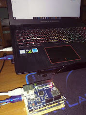
}2. Connect your Arduino board to the PC with a LAN cable.
3. If it is connected, it would be better if we check the connection first by "pinging" the Arduino board via CMD on the Client PC.
4. The next step is to open the VTScada software that we installed earlier. Wait a while (usually the initial opening is rather long, so you have to be patient).
5. Once open, usually if you have never created an application, the Add Application Wizzard window will appear immediately, click next.
6. Select Quick Add, and give the application a name whatever we want. Click Next.
7. click Finish ( Start Application Now).
Wait for the loading process to finish and the main page of the application that we are going to create appears, there are several display examples that we can reference in making our application later.
When the display appears, now the next step is to create a "TAG". Then click new so that a new window appears.
Click Port è TCP/IP Port
Then the name settings, IP Address (according to what we flash on Arduino) and port (for the 502 modbus port). Then click OK.
After the port, we make the modbus driver. By right-clicking the PORT, then clicking NEW CHILD èDriversèMobus Compatible Device, a new window will appear, enter the driver name (don't use spaces), and in the options tab check Open Modbus TCP.
Connection settings are complete, the next step is tagging, now here we are required to be creative and save tags, so that our application can be maximized. Okay, before I explain the relationship between tags in the Arduino IDE and tags in VTScada. Arduino tags use Mb.R [n] for analog data communication (ADC) and Mb.C [n] for digital data communication where n is a register, and registers on the Arduino IDE start from 0, for example Mb.R [0], Mb .R [1], Mb.C [0], Mb.C [1], etc. While the tag on VTScada uses 4000n for analog data and n for digital data, and the register on VTScada starts from 1, so for Mb.R [0] in Arduino it is 40001 in VTScada, and if Mb.C [1] is on Arduino then 2 on VTScada.
Okay let's move on to Tag creation. Right click on the driver that we created earlier, then click new ChildèAnalogsèAnalog Status. Then the settings are as shown below.
Then do the same thing to create a new digital status ChildèDigitalsèDigital Status, and the settings are as shown below. Then click OK and close the browser tag window.
After finishing tagging, then let's design the display by clicking Idea Studio, and make analog and digital displays according to your wishes.
Double click on the component to tag it to the browser tag that we created earlier
Do the same with each component.
Done, our application is ready,

 Software :


0 Comments