ILI9341 adalah driver SOC chip tunggal 262,144 warna untuk layar kristal cair A-TFT dengan resolusi 240RGBx320 Dots. Terdiri dari driver sumber 720- channel, driver gerbang 320-channel, GRAM 172.800 byte untuk grafis menampilkan data 240RGBx320 titik, dan sirkuit catu daya.
library
- Adafruit ILI9341
- Adafruit_GFX.h
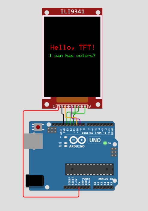
PROGRAM Menampilkan ILI9341
/*
Simple "Hello World" for ILI9341 LCD
https://wokwi.com/arduino/projects/308024602434470466
*/
#include "SPI.h"
#include "Adafruit_GFX.h"
#include "Adafruit_ILI9341.h"
#define TFT_DC 9
#define TFT_CS 10
Adafruit_ILI9341 tft = Adafruit_ILI9341(TFT_CS, TFT_DC);
void setup() {
tft.begin();
tft.setCursor(26, 120);
tft.setTextColor(ILI9341_RED);
tft.setTextSize(3);
tft.println("Hello, TFT!");
tft.setCursor(20, 160);
tft.setTextColor(ILI9341_GREEN);
tft.setTextSize(2);
tft.println("I can has colors?");
// Meme reference: https://english.stackexchange.com/questions/20356/origin-of-i-can-haz
}
void loop() { }
[INFO PENDAFTARAN KAMPUS KESEHATAN PMI KOTA SEMARANG]
Siapa nih yang punya cita-cita menjadi seorang tenaga kesehatan ? Berbicara
mengenai Program Studi Kesehatan tentu kita tahu bahwa prodi ini adalah
salah satu jurusan favorit di Indonesia dan juga merupakan cabang sains yang
berkembang pesat dalam peradaban manusia.
- Teknologi Bank Darah
- Rekam Medis & Informasi Kesehatan
- Teknik Elektromedik

Wujudkan cita-citamu bersama kami.Penerimaan Mahasiswa Baru Program Diploma POLITEKNIK BINA TRADA SEMARANG
Tahun 2023/2024.Program Diploma bertujuan menghasilkan lulusan di bidang Kesehatan yang
terkemuka , berkualitas, profesional dan mengabdi pada kepentingan
kemanusiaan.
Jadi tunggu apa lagi ? mari bergabung dengan Prodi Kesehatan. Caranya
gampang, #daftardarirumah saja dengan mengakses langsung website
pmb.polbitrada.ac.id.
More info PMB :
website :
polbitrada.ac.id
website pmb :
pmb.polbitrada.ac.id
profile Kampus : youtube
Call centre WA : 08112920076
Mari TUMBUH dan BERKEMBANG bersama kami di POLBITRADA SEMARANG!
Dimmer Circuit
The dimmer circuit is a circuit that functions to adjust the light intensity of the Light Emitting Diode (LED). In addition to adjusting the intensity of the LED, this circuit can basically also be used to adjust the speed of a DC motor.
This circuit is built from the basic principle of a pulse width modulator or PWM (Pulse Width Modulation) compared to a latch circuit.
LED lights are electronic components that function to emit light. This lamp is widely used in electronics projects because of its small size and energy saving and uses less power.
A standard LED lamp only requires a current of 10mA to 20mA with a working voltage of 2 to 3 volts.
PWM CIrcuit
The PWM circuit is a circuit that functions to adjust the width of a signal in the form of a digital pulse. This circuit will set the time period of the High Signal and Low Signal without affecting the frequency of the signal.
This High and Low period will later be compared with the logic level of the Latch and then used to adjust the intensity of the LED light.
The Latch circuit itself is a circuit that functions to hold an input value until the value is reset or changed. This circuit uses a Multivibrator component. The logic level of Latch will be compared with the PWM then the result will determine the intensity of the LED light.
Material :
- IC 555 (1)
- IC 4013 (5)
- IC AND Gate 7408 (1)
- IC 4028 (1)
- IC 7485 (1)
- Diode 4148 (1)
- Transistor NPN BC 337 (1)
- Resistor 4K7 (2)
- Resistor 10K (3)
- Resistor 1K (2)
- Kapasitor 100n (1)
- Push button Switch (2)
- LED 5mm (4)
Program Proteus can download
here